Introduction
Modern power systems are more complex than ever. With the global transition toward clean energy, electrification of industries, and growing digital demand, voltage constancy has become a key concern for utilities and industries alike. To maintain level power flow and optimal voltage levels, engineers rely deeply on reactive power recompense—enter the Static Var Compensator (SVC).
An SVC is a dynamic, high-speed device that stabilizes voltage by vaccinating or absorbing reactive power. This article offers a comprehensive look into the fundamentals of SVCs, highlighting their role in voltage stability, design principles, functional components, control strategies, and practical applications.
Understanding Voltage Stability and Reactive Power
Before diving into SVCs, let’s clarify the concepts of voltage stability and reactive power, which are vital for grid performance.
Reactive Power (Q)
Unlike active power (P), which does useful work (like lighting a bulb or turning a motor), reactive power:
- Provisions the voltage across inductive and capacitive components
- Is indispensable for magnetic field formation in transformers and motors
- Doesn’t transfer energy but enables energy flow
Reactive power is measured in volt-amperes reactive (VAR), and it guarantees that voltage levels remain strong throughout a power network.
Voltage Stability
A system is voltage-stable when it can maintain acceptable voltages across all buses under normal and stressed conditions (e.g. sudden load changes or faults). Voltage collapse or instability can lead to:
- Power outages
- Equipment damage
- Operational inefficiencies
Maintaining voltage stability requires real-time reactive power management, and that’s where SVCs prove invaluable.
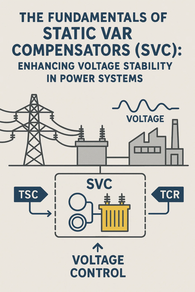
🔧 What Is a Static Var Compensator (SVC)?
A Static Var Compensator is a shunt-connected FACTS (Flexible AC Transmission System) device that provides reactive power compensation. Unlike traditional capacitor banks or synchronous condensers, an SVC offers:
- Fast dynamic response
- Electronic switching (thyristors)
- Real-time control
By constantly monitoring grid voltage and adjusting reactive power flow, SVCs control voltages at their connection point, improving power quality and system reliability.
Anatomy of an SVC System
An SVC integrates multiple components designed to work melodiously for reactive power control.
| Component | Function |
| Thyristor-Controlled Reactor (TCR) | Absorbs reactive power by controlling the current through an inductor |
| Thyristor-Switched Capacitor (TSC) | Injects reactive power using switched capacitor banks |
| Fixed Capacitors (FC) | Provide base reactive power without control |
| Harmonic Filters | Eliminate switching harmonics manufactured by thyristors |
| Voltage Sensors | Monitor bus voltage in real time |
| Control System | Executes logic and triggers thyristor operation |
Each part contributes to the exactness and reliability of the SVC.
How an SVC Functions in Real-Time
SVCs dynamically adjust to changing grid conditions through a feedback loop:
1. Voltage Detection
Sensors amount the voltage at the bus where the SVC is connected. This data is continuously Z into the controller.
2. Deviation Assessment
The measured voltage is compared against a set reference (typically ±5% of nominal). If deviations are noticed:
- Low voltage → Inject capacitive VARs
- High voltage → Absorb inductive VARs
3. Controller Response
Using procedures like PID or unsure logic, the controller determines the required reactive compensation.
4. Thyristor Triggering
Based on the control signal, thyristors are fired:
- In TCRs: firing angle controls current through reactor
- In TSCs: capacitors are switched in/out
5. Harmonic Management
Since thyristors generate harmonics during switching, inert filters or tuned reactors are employed to maintain power quality.
Common Configurations of SVCs
The performance of an SVC is largely verbalized by its configuration. Below are the primary types:
TCR-Based Configuration
- Features a continuously variable reactor
- Offers fine control for absorption of reactive power
- High harmonic content requires more filtering
TSC-Based Configuration
- Uses discrete switching of capacitors
- Fast response time
- Suitable for capacitive reactive power injection only
TCR + TSC Combination
- Provides full reactive power compensation (both injection and absorption)
- Balanced control and adaptability
- Widely used in complex grid environments
TCR + Fixed Capacitor Setup
- Simplified system with continuous absorption and fixed injection
- Lower cost but reduced flexibility
Each configuration is custom-made to specific grid conditions, budget restraints, and performance expectations.
Control Strategies for SVC Operation
The intelligence behind an SVC lies in its controller logic. Different strategies are used to manage gunfire angles and switching decisions:
| Control Method | Description |
| PID Control | Simple feedback mechanism balancing proportional, integral, and imitative actions |
| Fuzzy Logic | Rule-based system ideal for nonlinear and uncertain environments |
| Model Predictive Control (MPC) | Predicts future grid behavior and optimizes control actions |
| Neural Networks & AI | Machine learning approaches that adapt and evolve based on grid patterns |
Often, hybrid controllers are implemented to combine stability and adaptability.
Performance Metrics of SVCs
To evaluate the effectiveness of an SVC, engineers examine several technical parameters:
| Metric | Ideal Range or Description |
| Response Time | Typically less than 20–30 ms for transient voltage correction |
| Control Accuracy | Voltage maintained within ±1–2% of nominal |
| Harmonic Distortion | Total harmonic distortion < 3% using appropriate filters |
| Voltage Sag Mitigation | Capability to inject VARs during fault or load surge |
| Fault Ride-Through | Ability to remain operational during grid disturbances |
| Reliability & MTBF | High mean-time-between-failures with redundant components |
These metrics are central to ensuring SVCs perform reliably in real-world conditions.
Real-World Applications of SVCs
SVCs are versatile and used across diverse sectors:
Industrial Facilities
Heavy machines like arc heaters and compressors cause voltage fluctuations. SVCs stabilize voltage and protect equipment.
Renewable Energy Plants
Wind and solar generation present variability. SVCs mitigate voltage dips and improve fault acceptance.
Rail Networks
Electric trains draw large currents during acceleration. SVCs ensure voltage stability across traction substations.
Urban Substations
Compact city grids with fluctuating demand rely on SVCs to maintain consistent voltage levels.
Oil & Mining Operations
Large motors and start-stop cycles demand dynamic reactive power support, which SVCs provide efficiently.
Planning and Designing an SVC System
Effective SVC deployment involves:
Site Assessment
Evaluate voltage fluctuation patterns, fault history, and nearby equipment.
Load Flow and Harmonic Studies
Simulation models (e.g. ETAP, DIgSILENT, PSCAD) help determine VAR needs and harmonic mitigation strategies.
Equipment Sizing
Determine required VAR capacity (typically in MVAr), based on reactive power demand and system voltage level.
Protection and Coordination
Integrate protective relays, surge arresters, and coordination with other voltage devices (e.g. OLTC, capacitor banks).
Control Integration
Design control logic that interfaces with SCADA, substation automation, and power quality monitoring systems.
Proper planning ensures the SVC enhances grid stability without unintended disruptions.
Challenges in SVC Implementation
While SVCs offer high performance, engineers face some hurdles:
Harmonics
TCRs especially produce harmonics—requiring careful filter design.
Coordination Failure
Improper interaction with nearby reactive power devices can cause voltage hunting or control instability.
Environmental Exposure
Outdoor installations demand robust enclosures, insulation, and passive cooling systems.
Cybersecurity Risks
Digital controllers must be protected against spoofing, hacking, and unauthorized access.
Mitigating these risks ensures long-term operational success.
Future of SVCs in Smart Grids
The evolution of SVCs aligns with broader smart grid innovations:
- AI-Powered Control: Predictive voltage regulation using grid-wide data
- Modular and Scalable Designs: Plug-and-play SVC units for distributed networks
- Digital Twin Integration: Virtual models for diagnostics and performance tuning
- Renewable Synergy: Seamless integration with solar inverters, wind turbines, and battery energy storage systems
- Cloud Connectivity: Remote firmware updates and performance analytics
With these advancements, SVCs will transition from reactive compensators to intelligent grid partners.
Final Thoughts
Static Var Compensators may not be flashy—but they’re foundational to resilient power systems. By rapidly adjusting reactive power and keeping voltage levels within best bounds, SVCs stop blackouts, reduce losses, and protect infrastructure.