🔍 Introduction
Electrical circuits are the foundation of modern electronics, and understanding series and parallel circuits is essential for analyzing circuit behavior. These configurations determine how components share voltage and current, affecting performance and efficiency.
💡 Series Circuits
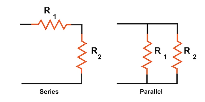
In a series circuit, all components are connected end-to-end, forming a single path for current flow.
✅ Current remains the same throughout the circuit.
✅ Voltage divides among components based on their resistance.
✅ Total resistance is the sum of individual resistances:
[ R_{\text{total}} = R_1 + R_2 + R_3 ]
Example: A string of holiday lights—if one bulb fails, the entire circuit breaks.
🔁 Parallel Circuits
In a parallel circuit, components are connected across common points, creating multiple paths for current flow.
✅ Voltage remains the same across all branches.
✅ Current divides among components based on resistance.
✅ Total resistance is calculated using:
[ \frac{1}{R_{\text{total}}} = \frac{1}{R_1} + \frac{1}{R_2} + \frac{1}{R_3} ]
Example: Household wiring—if one appliance stops working, others remain unaffected.
🏆 Key Differences
| Feature | Series Circuit | Parallel Circuit |
|---|---|---|
| Current | Same throughout | Divides among branches |
| Voltage | Divides among components | Same across all branches |
| Resistance | Sum of all resistances | Reciprocal sum of resistances |
| Failure Impact | Entire circuit stops | Other branches continue working |
🏁 Conclusion
Understanding series and parallel circuits is crucial for designing efficient electrical systems. Series circuits are useful for voltage division, while parallel circuits ensure consistent voltage and reliable operation.
Want to explore more? You can check out this guide for a deeper dive! 🚀 Let me know if you need further clarification! ⚙️🔍