Introduction
Modern electrical grids are under growing pressure—from surging demand and variable renewables to fast-acting industrial loads. In this landscape, reactive power compensation isn’t just technical jargon—it’s a necessity for grid stability and quality. That’s where Static Var Compensators (SVCs) step in: dynamic systems that regulate voltage in real time.
But not all SVCs are built the same. Their configurations vary based on application, performance needs, and design philosophy. This guide explores the different SVC setups in detail—breaking down their components, architectures, strengths, and use cases—so engineers and energy professionals can make informed decisions.
Why SVC Configuration Matters
At its core, an SVC adjusts the amount of reactive power in the system to stabilize voltage. It does this by either:
- Absorbing reactive power when voltage is high
- Injecting reactive power when voltage is low
The way an SVC accomplishes this depends heavily on its configuration—the combination and arrangement of reactors, capacitors, thyristors, filters, and control logic.
Correct configuration affects:
- Response speed
- Voltage regulation accuracy
- Harmonic performance
- Cost and footprint
- Reliability and maintenance
So let’s break down the options.
Core Components in SVC Architecture
Before diving into configurations, let’s identify the building blocks of SVCs:
| Component | Description |
|---|---|
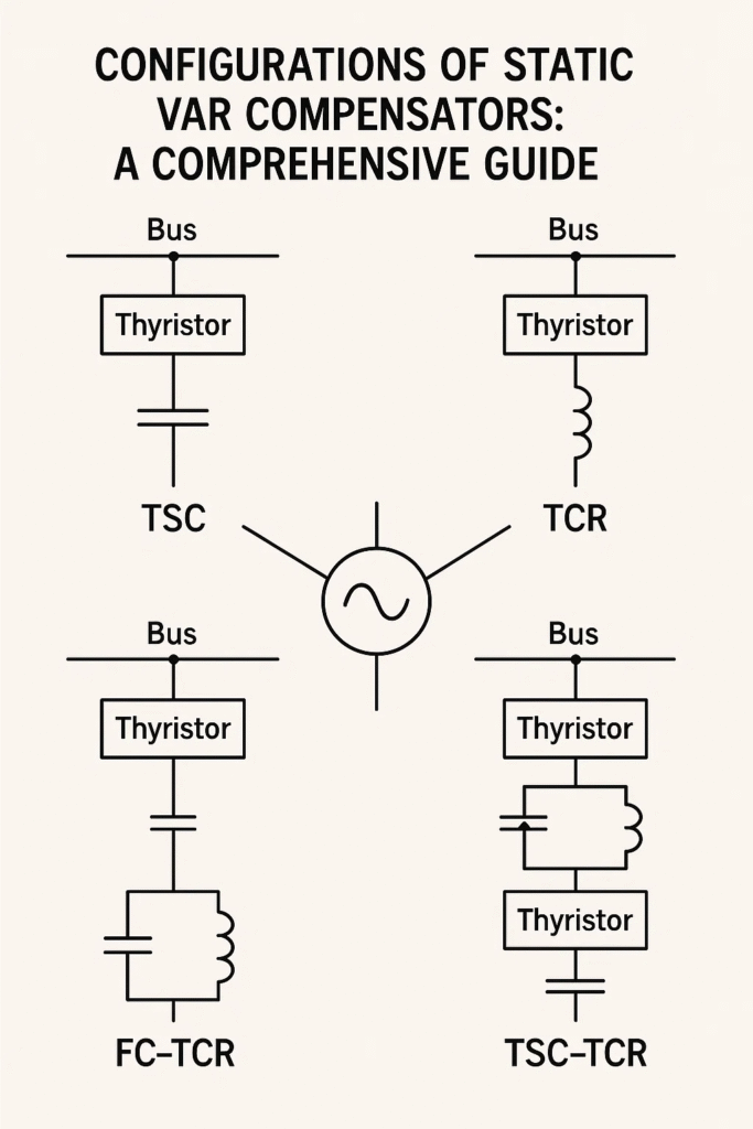
| Thyristor-Controlled Reactor (TCR) | Variable reactor controlled via firing angle of thyristors |
| Thyristor-Switched Capacitor (TSC) | Capacitor banks switched in/out with thyristors for fast response |
| Fixed Capacitor (FC) | Permanently connected capacitor providing base reactive power |
| Harmonic Filters | Tuned components that absorb unwanted harmonics from thyristor switching |
| Voltage Sensors | Measure grid voltage for feedback and control |
| Control System | Executes control strategy to trigger reactive power changes |
Different configurations mix and match these components to optimize system behavior.
Common SVC Configurations
Here are the most widely implemented types of SVC setups in grid and industrial environments.
1. TCR-Based SVC (Thyristor-Controlled Reactor)
Architecture:
- Includes a fixed capacitor and a TCR
- TCR’s reactor current is controlled continuously via thyristor firing angle
- Used to absorb excess reactive power
Advantages:
- Smooth and continuous control of reactive power
- Effective in correcting voltage rise due to light load
Challenges:
- Generates significant harmonics
- Slower response compared to TSC-based systems
Applications:
- Long transmission lines
- Lightly loaded substations
2. TSC-Based SVC (Thyristor-Switched Capacitor)
Architecture:
- Bank of capacitors switched via thyristors
- No continuously variable control—capacitors are switched in steps
Advantages:
- Extremely fast response (milliseconds)
- Lower harmonic generation compared to TCR
Challenges:
- Can’t absorb reactive power—only injects it
- Discrete steps can cause control resolution issues
Applications:
- Wind farms
- High-speed rail systems
3. Combined TCR-TSC SVC
Architecture:
- Combines TCR and TSC modules
- Provides both reactive power absorption and injection
Advantages:
- Full dynamic range of reactive power control
- Balances fast response with continuous control
Challenges:
- More complex control logic
- Higher cost and footprint
Applications:
- Industrial facilities with variable load
- Substations requiring precise voltage control
4. TCR with Fixed Capacitor
Architecture:
- Basic configuration with fixed capacitor and TCR only
- TCR modulates reactive power while capacitor stays connected
Advantages:
- Simple and cost-effective
- Ideal for small systems
Challenges:
- Fixed capacitor may overcompensate at light load
- Limited flexibility compared to TSC
Applications:
- Rural substations
- Legacy systems
5. Advanced Hybrid Systems
Architecture:
- Combines SVC with other FACTS devices like STATCOM
- May include energy storage (e.g., BESS) or digital control platforms
Advantages:
- Extremely responsive
- Grid-forming capabilities
- Can operate in weak grids and under fault conditions
Challenges:
- Highly complex design
- Expensive and requires high-end control platforms
Applications:
- Smart grids
- Renewable-heavy zones
- Microgrids
Comparative Overview of Configurations
Here’s a quick comparison matrix to visualize configuration differences:
| Configuration | Response Time | Harmonics | Reactive Power Range | Cost | Complexity |
|---|---|---|---|---|---|
| TCR Only | Medium | High | Absorption only | Low | Moderate |
| TSC Only | High | Low | Injection only | Medium | Moderate |
| TCR + TSC | High | Moderate | Full range | High | High |
| TCR + FC | Medium | High | Partial | Low | Low |
| Hybrid (SVC + STATCOM) | Ultra High | Very Low | Full + Storage Support | Very High | Very High |
Selection Criteria for SVC Configuration
When choosing the ideal setup for a specific grid application, several factors must be considered:
1. Grid Conditions
- Weak grids may need faster control → opt for TSC or hybrid systems
- Strong grids may tolerate harmonic-rich TCR setups
2. Load Profile
- Constant loads can work with fixed compensation
- Highly variable or cyclic loads require dynamic control
3. Space Constraints
- TCRs require bulky reactors
- Compact installations favor TSC or hybrid setups
4. Budget
- Capital-intensive hybrid systems must justify ROI
- TCR + FC setups are ideal for cost-sensitive projects
5. Maintenance Requirements
- Complex systems need routine diagnostics and skilled operators
- Simpler configurations offer low maintenance
Real-World Examples
Steel Plant SVC Upgrade
A steel facility in Southeast Asia faced voltage instability during arc furnace operations. Initial configuration included a TCR + FC setup, but voltage swings were too severe.
Engineers upgraded to a combined TCR-TSC configuration, introducing dynamic capacitor banks and digital control.
Outcome: Voltage remained within ±3% bounds even during peak load. Harmonics reduced with additional filters.
Wind Farm Reactive Control
A wind farm in Europe used TSC-based SVCs to inject reactive power during generation surges. However, grid codes mandated absorption capability during fault events.
The team upgraded to a hybrid SVC-STATCOM system, enabling bi-directional reactive compensation.
Outcome: Grid compliance achieved, fault ride-through improved, and voltage stability strengthened.
Future Trends in SVC Configurations
As power systems evolve, SVC architectures will become:
- More modular (plug-and-play capacitor/reactor modules)
- Digitally intelligent with AI and predictive control
- Integrated with renewable sources and grid storage
- Capable of self-diagnostics and remote configuration
Digital twin technology, where a virtual model simulates SVC behavior, will allow engineers to test and tweak configurations without physical intervention.
Final Thoughts
The configuration of a Static Var Compensator isn’t just a technical choice—it’s a strategic decision that affects grid performance, operational efficiency, and economic viability. Whether you’re stabilizing voltage in an urban substation or managing reactive power in a remote wind farm, the right configuration makes all the difference.