Introduction
Electricity powers our modern world, but the journey from generation to ingesting is far more complex than flicking a switch. One of the most dangerous aspects of this journey is the transmission of electrical power over long distances, especially through Alternating Current (AC) transmission lines. Alongside this, managing reactive power becomes essential to ensure efficiency, stability, and dependability in power systems.
In this blog, we’ll explore the fundamentals of AC transmission lines, the challenges they face, and how reactive power compensation plays a vital role in overcoming those challenges.
Understanding AC Transmission Lines
What Is an AC Transmission Line?
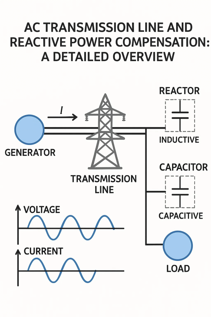
An AC transmission line is a system of conductors used to transport electrical energy from power generation stations to substations and eventually to consumers. These lines operate using alternating current, which reverses direction periodically—typically 50 or 60 times per second (50 Hz or 60 Hz).
Key Components of AC Transmission Lines
- Conductors: Usually made of aluminum or copper, these carry the electrical current.
- Insulators: Prevent current from leaking to the ground or between conductors.
- Towers and Poles: Support the conductors and maintain safe clearances.
- Substations: Border points for voltage transformation, switching, and protection.
Types of Transmission Lines
| Type | Voltage Range | Application |
| Short Line | < 80 km | Local distribution |
| Medium Line | 80–250 km | Regional transmission |
| Long Line | > 250 km | Inter-regional or national grid |
Electrical Parameters of AC Transmission Lines
AC transmission lines are characterized by four primary electrical parameters:
- Resistance (R): Causes power loss due to heat.
- Inductance (L): Stores energy in magnetic fields; contributes to reactive power.
- Capacitance (C): Stores energy in electric fields; also contributes to reactive power.
- Conductance (G): Represents leakage currents; usually negligible.
These parameters affect the voltage regulation, power losses, and stability of the transmission system.
The Concept of Reactive Power
What Is Reactive Power?
Reactive power (measured in VARs – Volt-Ampere Reactive) is the helping of electricity that vacillates between the source and the load but does not perform any real work. It rises due to the presence of inductance and capacitance in the system.
- Real Power (P): Does actual work (measured in Watts).
- Reactive Power (Q): Supports voltage levels (measured in VARs).
- Apparent Power (S): Combination of real and reactive power (measured in VA).
The relationship is given by:
S = \sqrt{P^2 + Q^2}
Why Is Reactive Power Important?
Reactive power is essential for:
- Maintaining voltage levels across the network.
- Allowing the transfer of real power.
- Preventing voltage collapse and instability.
Without passable reactive power, even a system with appropriate real power can fail to operate properly.
Challenges in AC Transmission
1. Voltage Drop
Long transmission lines knowledge voltage drops due to inductive reactance. This can lead to poor voltage regulation and affect sensitive equipment.
2. Power Losses
Resistance and reactance cause energy losses, reducing overall efficiency.
3. Stability Issues
Reactive power inequity can lead to voltage instability, oscillations, and even blackouts.
4. Load Variation
Changing loads can cause reactive power demand to vary, requiring dynamic compensation.
Reactive Power Compensation Techniques
Reactive power compensation involves adding devices to the transmission system that either absorb or inject reactive power to maintain voltage stability and improve efficiency.
Types of Compensation
| Type | Description | Example Devices |
| Shunt Compensation | Connected in parallel to the line; regulates voltage | Capacitors, Reactors, STATCOM |
| Series Compensation | Connected in series; improves power transfer capability | Series Capacitors |
| Dynamic Compensation | Adjusts in real-time based on system needs | SVC, STATCOM, D-FACTS |
Shunt Compensation
Shunt Capacitors
- Inject reactive power to counter inductive loads.
- Improve power factor and voltage profile.
- Commonly used in delivery networks.
Shunt Reactors
- Absorb excess reactive power in lightly loaded lines.
- Prevent overvoltage conditions.
Static VAR Compensator (SVC)
- Uses thyristor-controlled reactors and capacitors.
- Provides fast and continuous reactive power control.
Static Synchronous Compensator (STATCOM)
- Voltage-source converter-based device.
- Offers superior dynamic performance compared to SVC.
Series Compensation
Series Capacitors
- Reduce the net inductive reactance of the line.
- Increase power transfer capability.
- Improve system stability.
However, they can introduce issues like sub-synchronous resonance, which must be diminished through proper design.
Advanced Compensation Technologies
Flexible AC Transmission Systems (FACTS)
FACTS devices enhance controllability and increase power transfer capability. Examples include:
- UPFC (Unified Power Flow Controller): Controls voltage, impedance, and phase angle.
- D-FACTS: Distributed FACTS devices for modular compensation.
Energy Storage Systems
Battery-based systems can provide both real and reactive power, helping in grid stabilization and peak shaving.
Benefits of Reactive Power Compensation
- Improved Voltage Stability: Maintains voltage within acceptable limits.
- Enhanced Power Transfer: Allows more power to be transmitted over existing lines.
- Reduced Losses: Minimizes I²R losses and improves efficiency.
- Better Power Quality: Reduces flicker, harmonics, and voltage fluctuations.
- Optimized Asset Utilization: Delays the need for infrastructure upgrades.
Real-World Applications
1. Urban Power Grids
High load density and changing demand require dynamic compensation using STATCOMs and SVCs.
2. Renewable Energy Integration
Wind and solar farms introduce changeability and reactive power challenges. Compensation ensures grid stability.
3. Industrial Facilities
Large motors and inductive loads demand power factor correction through capacitor banks and SVCs.
Case Study: Reactive Power Compensation in India’s Power Grid
India’s vast transmission network faces challenges due to long distances and high demand. The deployment of SVCs, STATCOMs, and series capacitors has meaningfully improved grid reliability and reduced outages.
For example, the Power Grid Corporation of India has implemented FACTS devices across key strips to manage reactive power and enhance transmission capacity.
Future Trends
- AI-Based Grid Management: Predictive analytics for reactive power needs.
- Hybrid Compensation Systems: Combining multiple technologies for optimal performance.
- Smart Grids: Real-time monitoring and control of reactive power flow.
- Decentralized Compensation: Using distributed energy resources for local voltage support.
Conclusion
AC transmission lines are the veins of our electrical infrastructure, carrying energy across vast distances to power homes, industries, and cities. However, their performance is deeply influenced by the invisible but vital element of reactive power. Without proper management of reactive power, even the most healthy transmission systems can hurt from voltage instability, power losses, and reduced efficiency.
Reactive power compensation is not just a technical fix—it’s a strategic requirement. From simple capacitor banks to urbane FACTS devices like STATCOMs and UPFCs, these technologies ensure that power systems remain stable, efficient, and resilient. They allow us to transmit more power over existing infrastructure, integrate renewable energy sources, and uphold high-quality electricity supply in the face of growing demand.