Introduction
In the ever-evolving landscape of electrical power systems, the demand for efficient, stable, and flexible transmission has never been greater. As grids become more complex and renewable energy sources are integrated, traditional methods of power flow control fall short. Enter Flexible AC Transmission Systems (FACTS)—a suite of technologies designed to enhance the controllability and increase the power transfer capability of networks.
Among these, the Thyristor-Controlled Series Capacitor (TCSC) stands out as a powerful tool for dynamic line compensation. It’s not just a capacitor—it’s a smart, responsive device that adjusts itself in real time to optimize power flow, stabilize voltage, and dampen oscillations.
Let’s dive into the mechanism, working principles, and real-world impact of TCSC.
What Is a TCSC?
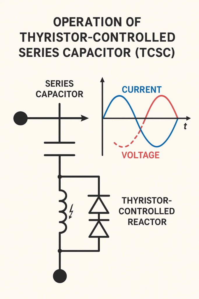
A Thyristor-Controlled Series Capacitor (TCSC) is a type of FACTS device installed in series with a transmission line. It consists of:
- A Fixed Capacitor (FC) – provides base capacitive compensation.
- A Thyristor-Controlled Reactor (TCR) – modulates the effective reactance.
- Control Electronics – governs the thyristor firing angle to adjust impedance.
The TCSC dynamically alters the line impedance by controlling the conduction angle of thyristors, enabling real-time compensation of reactive power.
Why Use TCSC?
TCSC offers several advantages over traditional fixed series capacitors:
| Feature | Fixed Series Capacitor | TCSC |
| Control | Static | Dynamic, real-time |
| Response Time | Slow | Fast (milliseconds) |
| Power Flow Optimization | Limited | Highly efficient |
| Oscillation Damping | Minimal | High |
| SSR Mitigation | No | Yes |
Working Principle of TCSC
At its core, TCSC operates by modulating the impedance of the transmission line. This is achieved by varying the firing angle (α) of the thyristors in the TCR, which changes the inductive reactance X_L(α). The total impedance of the TCSC is:
X_{TCSC} = X_C + X_L(α)
Where:
- X_C is the reactance of the fixed capacitor.
- X_L(α) is the variable inductive reactance controlled by thyristor firing.
By adjusting α, the TCSC can: - Decrease impedance to allow more power flow.
- Increase impedance to dampen oscillations or limit power flow.
Modes of Operation
TCSC operates in three primary modes, each with distinct characteristics:
- Blocked Mode (Fixed Capacitor Mode)
- Thyristors are OFF.
- No current flows through the TCR.
- TCSC behaves like a fixed capacitor.
- Used during steady-state conditions.
2. Bypass Mode (Inductive Mode)
- Thyristors are fully ON.
- Capacitor is bypassed.
- Net impedance is inductive.
- Used during faults or voltage fluctuations.
3. Partially Conducting Mode (Controlled Compensation)
- Thyristors conduct partially.
- Impedance is dynamically adjusted.
- Most common mode in normal operation.
- Enables smooth control of power flow.
Impedance Control Mechanism
The key to TCSC’s flexibility lies in its ability to modulate impedance through thyristor switching. Here’s how it works:
- Firing angle (α) determines the conduction period of thyristors.
- As α changes, the inductive reactance X_L(α) varies.
- This alters the net impedance X_{TCSC}, affecting power flow.
The control system uses feedback from voltage and current sensors to adjust α in real time, ensuring optimal performance.
Technical Insights
Resonance Considerations
- TCSC must avoid operating in the resonant region, where X_C = X_L.
- Resonance can lead to uncontrolled oscillations and system instability.
- Control algorithms ensure α stays within safe limits.
V-I Characteristics - In capacitive mode, voltage increases with current.
- In inductive mode, voltage decreases with current.
- The TCSC controller maintains desired voltage levels by adjusting α.
Benefits of TCSC
- Enhanced Power Transfer
- Reduces line reactance.
- Allows more power to flow through existing infrastructure.
2. Improved Voltage Stability
- Injects reactive power as needed.
- Prevents voltage collapse in heavily loaded corridors.
3. Damping of Oscillations
- Suppresses low-frequency oscillations.
- Enhances generator stability.
4. SSR Mitigation
- Prevents sub synchronous resonance (SSR) interactions.
- Protects turbine-generator shafts from damage.
5. Congestion Management
- Redirects power flow away from overloaded lines.
- Improves grid reliability.
Real-World Applications
TCSC is used in various sectors:
- High-Voltage Transmission: Enhances long-distance power transfer.
- Renewable Integration: Stabilizes output from wind and solar farms.
- Industrial Systems: Reduces voltage sags in heavy industries.
- Smart Grids: Enables intelligent power distribution.
Challenges and Limitations
Despite its advantages, TCSC faces some hurdles:
- High Initial Cost: Complex components and control systems.
- Harmonics: Thyristor switching introduces harmonics.
- Maintenance: Sensitive electronics require careful handling.
Future Trends
The future of TCSC is bright, with innovations on the horizon:
- AI-Based Controllers: Predictive optimization of power flow.
- Hybrid FACTS Devices: Combining TCSC with STATCOM or SVC.
- Advanced Semiconductors: Faster, more efficient thyristors.
Conclusion
The Thyristor-Controlled Series Capacitor (TCSC) is a game-changer in modern power systems. By offering dynamic, real-time control of line impedance, it enhances power transfer, stabilizes voltage, and mitigates dangerous oscillations.
As grids become smarter and more complex, TCSC will play a pivotal role in ensuring reliable, efficient, and resilient power delivery.
Would you like this blog formatted for publishing on a website or turned into a presentation?